- 您现在的位置:买卖IC网 > Sheet目录3831 > PIC18F4423-I/ML (Microchip Technology)IC PIC MCU FLASH 8KX16 44QFN
2009 Microchip Technology Inc.
DS39755C-page 35
PIC18F2423/2523/4423/4523
3.0
SPECIAL FEATURES OF THE
CPU
3.1
Device ID Registers
The Device ID registers are read-only registers. They
identify the device type and revision for device pro-
grammers and can be read by firmware using table
reads.
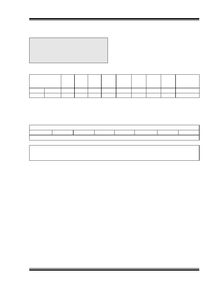
TABLE 3-1:
DEVICE IDs
Note:
For additional details on the Configuration
bits, refer to Section 23.1 “Configuration
Bits” in the “PIC18F2420/2520/4420/4520
Data Sheet” (DS39631). Device ID informa-
tion presented in this section is for the
PIC18F2423/2523/4423/4523 devices only.
File Name
Bit 7
Bit 6
Bit 5
Bit 4
Bit 3
Bit 2
Bit 1
Bit 0
Default/
Unprogrammed
Value
3FFFFEh DEVID1(1)
DEV3
DEV2
DEV1
DEV0
REV3
REV2
REV1
REV0
xxxx xxxx(2)
3FFFFFh DEVID2(1)
DEV11
DEV10
DEV9
DEV8
DEV7
DEV6
DEV5
DEV4
xxxx xxxx(2)
Legend:
x = unknown, u = unchanged, — = unimplemented. Shaded cells are unimplemented, read as ‘0’.
Note 1:
DEVID registers are read-only and cannot be programmed by the user.
2:
See Register 3-1 and Register 3-2 for DEVID1 and DEVID2 values.
REGISTER 3-1:
DEVID1: DEVICE ID REGISTER 1 FOR PIC18F2423/2523/4423/4523
RR
R
DEV3
DEV2
DEV1
DEV0
REV3
REV2
REV1
REV0
bit 7
bit 0
Legend:
R = Read-only bit
P = Programmable bit
U = Unimplemented bit, read as ‘0’
-n = Value when device is unprogrammed
u = Unchanged from programmed state
bit 7-4
DEV<3:0>: Device ID bits
1101 = PIC18F4423
1001 = PIC18F4523
0101 = PIC18F2423
0001 = PIC18F2523
bit 3-0
REV<3:0>: Revision ID bits
These bits are used to indicate the device revision.
发布紧急采购,3分钟左右您将得到回复。
相关PDF资料
PIC16F874A-I/P
IC MCU FLASH 4KX14 EE 40DIP
PIC18F87J60-I/PT
IC PIC MCU FLASH 64KX16 80TQFP
PIC24HJ128GP202-I/MM
IC PIC MCU FLASH 128K 28-QFN
PIC16F873-04/SO
IC MCU FLASH 4KX14 EE 28SOIC
PIC24FJ128GA106-I/PT
IC PIC MCU FLASH 64TQFP
AT87C51RD2-RLTUM
IC 8051 MCU 64K OTP 40MHZ 44VQFP
AT87C51RD2-RLTUL
IC 8051 MCU 64K OTP 30MHZ 44VQFP
PIC16F873-04/SP
IC MCU FLASH 4KX14 EE 28DIP
相关代理商/技术参数
PIC18F4423-I/P
功能描述:8位微控制器 -MCU 16KB 768bytes-RAM 36I/O RoHS:否 制造商:Silicon Labs 核心:8051 处理器系列:C8051F39x 数据总线宽度:8 bit 最大时钟频率:50 MHz 程序存储器大小:16 KB 数据 RAM 大小:1 KB 片上 ADC:Yes 工作电源电压:1.8 V to 3.6 V 工作温度范围:- 40 C to + 105 C 封装 / 箱体:QFN-20 安装风格:SMD/SMT
PIC18F4423-I/PT
功能描述:8位微控制器 -MCU 16KB 768bytes-RAM 36I/O RoHS:否 制造商:Silicon Labs 核心:8051 处理器系列:C8051F39x 数据总线宽度:8 bit 最大时钟频率:50 MHz 程序存储器大小:16 KB 数据 RAM 大小:1 KB 片上 ADC:Yes 工作电源电压:1.8 V to 3.6 V 工作温度范围:- 40 C to + 105 C 封装 / 箱体:QFN-20 安装风格:SMD/SMT
PIC18F4423-I/PT
制造商:Microchip Technology Inc 功能描述:8-Bit Microcontroller IC
PIC18F4423T-I/ML
功能描述:8位微控制器 -MCU 16KB 768bytes-RAM 36I/O RoHS:否 制造商:Silicon Labs 核心:8051 处理器系列:C8051F39x 数据总线宽度:8 bit 最大时钟频率:50 MHz 程序存储器大小:16 KB 数据 RAM 大小:1 KB 片上 ADC:Yes 工作电源电压:1.8 V to 3.6 V 工作温度范围:- 40 C to + 105 C 封装 / 箱体:QFN-20 安装风格:SMD/SMT
PIC18F4423T-I/PT
功能描述:8位微控制器 -MCU 16KB 768bytes-RAM 36I/O RoHS:否 制造商:Silicon Labs 核心:8051 处理器系列:C8051F39x 数据总线宽度:8 bit 最大时钟频率:50 MHz 程序存储器大小:16 KB 数据 RAM 大小:1 KB 片上 ADC:Yes 工作电源电压:1.8 V to 3.6 V 工作温度范围:- 40 C to + 105 C 封装 / 箱体:QFN-20 安装风格:SMD/SMT
PIC18F442-E/L
功能描述:8位微控制器 -MCU 16KB 768 RAM 34I/O RoHS:否 制造商:Silicon Labs 核心:8051 处理器系列:C8051F39x 数据总线宽度:8 bit 最大时钟频率:50 MHz 程序存储器大小:16 KB 数据 RAM 大小:1 KB 片上 ADC:Yes 工作电源电压:1.8 V to 3.6 V 工作温度范围:- 40 C to + 105 C 封装 / 箱体:QFN-20 安装风格:SMD/SMT
PIC18F442-E/ML
功能描述:8位微控制器 -MCU 16KB 768 RAM 34I/O RoHS:否 制造商:Silicon Labs 核心:8051 处理器系列:C8051F39x 数据总线宽度:8 bit 最大时钟频率:50 MHz 程序存储器大小:16 KB 数据 RAM 大小:1 KB 片上 ADC:Yes 工作电源电压:1.8 V to 3.6 V 工作温度范围:- 40 C to + 105 C 封装 / 箱体:QFN-20 安装风格:SMD/SMT
PIC18F442-E/P
功能描述:8位微控制器 -MCU 16KB 768 RAM 34I/O RoHS:否 制造商:Silicon Labs 核心:8051 处理器系列:C8051F39x 数据总线宽度:8 bit 最大时钟频率:50 MHz 程序存储器大小:16 KB 数据 RAM 大小:1 KB 片上 ADC:Yes 工作电源电压:1.8 V to 3.6 V 工作温度范围:- 40 C to + 105 C 封装 / 箱体:QFN-20 安装风格:SMD/SMT